RS485 Output Remotely Reading Gas Meters
RS485 Output Remotely Reading Gas Meters
RS485 Output Remotely Reading Gas Meters
- Detail
- Parameters
Overview
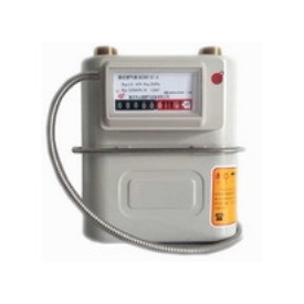
Shancheng RS485 Photoelectric Remotely Reading Gas Meters use very advanced micro-electronics technology. It owns lots of features, such as high integrated level, high measure accuracy, low power consumption, numbered rollers display, convenient installing etc. This technology is very good for domestic gas meter and industrial gas meters.
Working principal
This meter, through transmission type optical-to-electrical transducing, reads value of the numbered rollers in mechanical meters immediately. With photoelectric encoder technology, we treat each numbered rollers as a code wheel, the five infrared receiver tubes receive the infrared light sent from the numbered rollers and causes electrical level fluctuation to form a group of 5 digits code. After decoding, these codes will be sent to the computer and displays the same number in the numbered rollers of mechanical meter.
Technical Parameter
Power sauce: Volt: DC12V±2V
Current: 0.6mA
Working Environment: Temp: -5-+45℃
Humidity: 0-95%RH
Accuracy Grade: ISO4064 (Grade B)
Communicating Method: RS-485/MBUS
Transmitting Frequency: 1200baud
Max Communicating Distance: 1200m
Valve Parameter (Optional)
1. Basic Parameter
(1) Media: Natural Gas/LPG
(2) Flow Rate:0-6M3/h
(3) Pressure Range:0-5Kpa
(4) Working Temperature:-5-50℃
(5) Store Temperature: -10--35℃
(6) Humidity: 5-90%RH
(7) Pressure Loss: ≤50Pa
(8) Leak tightness: Under4.2KPa,leak amount less than 0.2L/H
2. Electric Parameter
(1) Valve working volt: DC2.5-6V
(2) Valve working current: ≤80mA
(3) Valve open time: ≤3S
(4) Valve close time: ≤3S
(5) Status switch contact resistance:1Ω
(6) Insulating resistance: 》20MΩ
(7) Valve open& close speed: 5-12times/min
3. Valve Usage Instruction
This Valve is 4 lines output type. Among the 4 lines, blue line is the opening valve positive (closing valve negative), white line is opening valve negative (closing valve positive), the rest two yellow lines is status switch lines.
Open valve process: The valve opening time must be controlledby the program and can not be manually control. Supply power to the motor, when the detecting device detected the valve is in the open position; you should add some time lag electricity (about 100ms) and then cut off the power. Valve opening time is 3S.
Close valve process: Supply power to the motor, when the detecting device detected the valve is in the close position; you should add some time lag electricity (about 100ms) and then cut off the power. Valve opening time is 3S.
Under lowest working volt condition, the volt supplied to open or close the valve cannot be less than 2.5V.
The valve is installed a travel switch inside. If open or close valve have finished and the valve is still execute opening or closing valve order, it may be destroyed. So using uncontrolled direct current power sauce to open or close valve is strictly forbidden.
The current supplied by the valve control circuit should be higher than motor’s peak particle current.